Bulbs
Flower Basics
Flower Beds & Specialty Gardens
Flower Garden
Garden Furniture
Garden Gnomes
Garden Seeds
Garden Sheds
Garden Statues
Garden Tools & Supplies
Gardening Basics
Green & Organic
Groundcovers & Vines
Growing Annuals
Growing Basil
Growing Beans
Growing Berries
Growing Blueberries
Growing Cactus
Growing Corn
Growing Cotton
Growing Edibles
Growing Flowers
Growing Garlic
Growing Grapes
Growing Grass
Growing Herbs
Growing Jasmine
Growing Mint
Growing Mushrooms
Orchids
Growing Peanuts
Growing Perennials
Growing Plants
Growing Rosemary
Growing Roses
Growing Strawberries
Growing Sunflowers
Growing Thyme
Growing Tomatoes
Growing Tulips
Growing Vegetables
Herb Basics
Herb Garden
Indoor Growing
Landscaping Basics
Landscaping Patios
Landscaping Plants
Landscaping Shrubs
Landscaping Trees
Landscaping Walks & Pathways
Lawn Basics
Lawn Maintenance
Lawn Mowers
Lawn Ornaments
Lawn Planting
Lawn Tools
Outdoor Growing
Overall Landscape Planning
Pests, Weeds & Problems
Plant Basics
Rock Garden
Rose Garden
Shrubs
Soil
Specialty Gardens
Trees
Vegetable Garden
Yard Maintenance
How to Install Lights on a Mower
How to Install Lights on a Mower. Some lawn mowers can be adapted for purposes other than cutting grass. For example, a riding mower may have attachments that allow it to serve as a lawn tractor or snowplow. Some of these purposes — such as plowing snow — may require using the mower at night or in the early-morning hours when it is dark...

Some lawn mowers can be adapted for purposes other than cutting grass. For example, a riding mower may have attachments that allow it to serve as a lawn tractor or snowplow. Some of these purposes � such as plowing snow � may require using the mower at night or in the early-morning hours when it is dark outside. If you plan to use a mower for such a purpose, you may want to install a headlight on it.
Things You'll Need
Drill
Surface-mount automotive fog lamp
Adjustable wrench
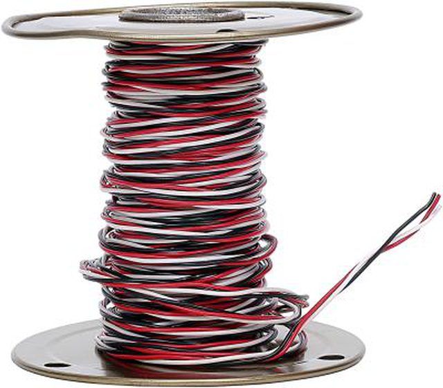
Spool of red electrical wire (16 AWG, stranded copper)
Self-stripping electrical tap connectors
Electrical pliers
Crimp-type ring terminals
Machine screws (size 10-32)
Machine nuts (size 10-32)
Soldering iron
Electronic solder
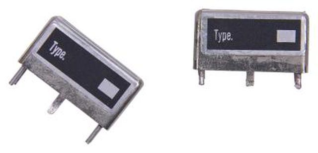
Automotive relay
Single-pole, single-throw switch
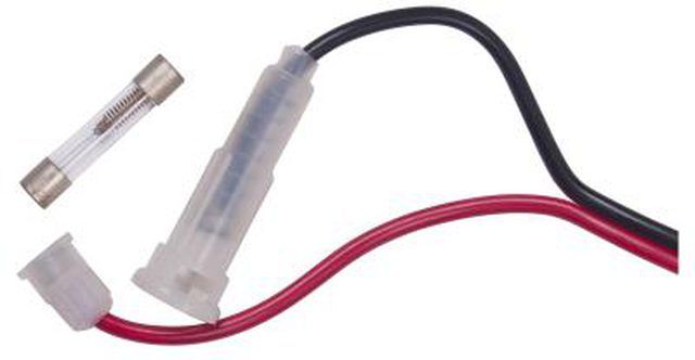
Inline glass fuse holder
10-amp automotive glass fuse
Drill a mounting hole in the front of the lawn mower frame. Loosen and remove the retaining nut from a surface-mount automotive fog lamp's mounting bolt. Insert the mounting bolt from the fog lamp into the hole. Screw the retaining nut on to the mounting bolt and use a wrench to tighten the nut so that the lamp is mounted firmly to the frame of the lawn mower.
Place the red wire from the fog lamp into the hole that is open on only one end (also known as the "tap wire" hole) on the first electrical tap connector. Place the loose end of the wire coming from a spool of red electrical wire into the bottom of the run channel (the hole on the wire splice connector that is open at both ends) on the first electrical tap connector. Crimp the metal U-contact down until the top of the connector is flush with the plastic case on the electrical tap connector. Close the hinged cover on the electrical tap connector until it snaps into place.
Use electrical pliers to strip 1/2 an inch of insulation from the end of the black wire on the fog lamp. Place a ring terminal over the black wire and crimp the terminal to the wire. Drill a small hole in the frame next to the fog lamp. Place the first machine screw shaft through both the ring terminal and the hole in the frame. Screw on the first machine nut and tighten the nut with the adjustable wrench.
Drill a hole in the tractor dashboard. Loosen the retaining nut from the shaft of the single pole, single throw switch. Insert the switch shaft through the hole. Tighten the retaining nut to the shaft so that the retaining nut holds the switch firmly to the tractor dashboard.
Drill a hole in the tractor frame approximately 1 foot from the lawn mower�s battery box. Insert the second machine screw through both the hole in the tractor frame and the mounting hole in the automotive relay. Screw on the second machine nut and tighten the nut using the adjustable wrench.
Route the spool of wire from the fog lamp to the relay. Cut the wire from the spool so that there are approximately 4 inches of slack from the fog lamp to the relay. Strip 1/2 an inch of insulation from the loose end of the wire. Melt a small drop of solder to both the loose end of the wire and to the "87" terminal on the relay. Use the soldering iron tip to smooth out the soldered joint until the joint is shiny and free of lumps.
Strip 1/2 an inch of insulation from the end of the wire on the wire spool. Solder this wire end to the "85" terminal on the relay. Route this wire to the back of the switch on the tractor dashboard, and cut the wire so that there are approximately 4 inches of slack between the tractor switch and the relay. Remove 1/2 an inch of insulation from the loose end of this wire and solder the wire to one of the switch terminals.
Strip 1/2 an inch of insulation from the end of the wire on the wire spool. Solder this wire end to the remaining switch terminal. Route this wire to the starter switch. Place the wire from the switch into the tap wire hole on the second electrical tap connector. Place the starter wire into the bottom of the run channel on the second electrical tap connector. Crimp the metal U-contact down until the top of the connector is flush with the plastic case on the electrical tap connector. Close the hinged cover on the electrical tap connector until it snaps into place.
Strip 1/2 an inch of insulation from one of the wire leads on the inline glass fuse holder. Solder the stripped lead to the "30" terminal on the relay. Place the unstripped lead from the fuse holder into the tap wire hole on the third electrical tap connector. Place the loose end of the wire from the wire spool into the bottom of the run channel on the third electrical tap connector. Crimp the metal U-contact down until the top of the connector is flush with the plastic case on the electrical tap connector. Close the hinged cover on the electrical tap connector until it snaps into place.
Drill a small hole in the battery box. Run the wire from the spool so that the wire reaches from the positive battery terminal to the relay. Cut the wire from the spool and strip 1/2 an inch of insulation from the free end of the wire. Crimp a ring terminal to the end of the wire. Route the wire through the hole and place the ring terminal near the positive battery terminal.
Use the wrench to loosen and remove the retaining nut on the positive battery terminal. Place the ring terminal over the retaining bolt on the positive battery terminal. Replace the retaining nut and tighten the nut to the retaining bolt. Insert the fuse into the fuse holder.
Tips & Warnings
The light will operate only when the engine is running. The switch obtains its power from the starter wire and will not turn the relay circuit on if the engine is stopped.


